
|
|
Make a Welded Die
| make welded die project.pdf |
Lesson Objectives
The student will be able to:
• Work safely using metalworking tools
• Use information from a drawing
• Perform accurate layout
• Cut and form materials using hand tools and power tools
• Join metal by welding processes
• Perform finishing techniques using hand tools and power tools
Estimated Time
Equipment/Machinery
• MIG welder (GMAW)
• Bench grinder
• Belt sander
• Drill press
• Bench vise
Personal Protective Equipment
• Welding coat • Welding gloves
• Welding helmet
Tools
• Welding magnets
• De-burring tool
• Hacksaw
• Metal file
• Machinist square
Scriber
• Hermaphrodite caliper
• Centre punch
Materials
• Mild steel flat stock ⅛" × 2" (or similar)
• Spray paint
• Sandpaper
The student will be able to:
• Work safely using metalworking tools
• Use information from a drawing
• Perform accurate layout
• Cut and form materials using hand tools and power tools
• Join metal by welding processes
• Perform finishing techniques using hand tools and power tools
Estimated Time
- 6 hours
- The time will depend on the students’ experience in the metalwork shop and the number of tools available to them.
Equipment/Machinery
• MIG welder (GMAW)
• Bench grinder
• Belt sander
• Drill press
• Bench vise
Personal Protective Equipment
• Welding coat • Welding gloves
• Welding helmet
Tools
• Welding magnets
• De-burring tool
• Hacksaw
• Metal file
• Machinist square
Scriber
• Hermaphrodite caliper
• Centre punch
Materials
• Mild steel flat stock ⅛" × 2" (or similar)
• Spray paint
• Sandpaper
Part 1: Layout and Cutting
1. Using a ruler and a scribe, make a mark at 2" on a piece of ⅛" × 2" mild steel flat stock.
2. Using a machinist square and scribe, make a line at the 2" mark perpendicular to the metal’s length, creating a 2" × 2" square.
3. Using a hacksaw, cut off the 2" x 2" piece just on the outside edge of the line.
4. Use a metal file to file both ends to the scribed line to be exactly 2" square
5. Repeat steps 1–4 five more times until you have six 2" × 2" pieces.
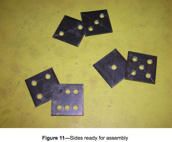
Each piece will require layout lines to produce one side of the six die sides (6a–6f).
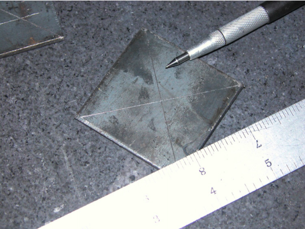
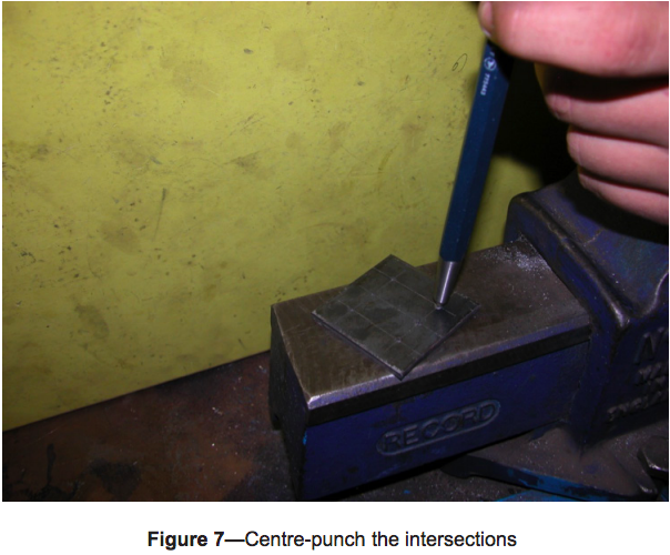
6. a. For #1, scribe an “X” from corner to corner to find the centre (Figure 1), then centre-punch the intersection.
2. Using a machinist square and scribe, make a line at the 2" mark perpendicular to the metal’s length, creating a 2" × 2" square.
3. Using a hacksaw, cut off the 2" x 2" piece just on the outside edge of the line.
4. Use a metal file to file both ends to the scribed line to be exactly 2" square
5. Repeat steps 1–4 five more times until you have six 2" × 2" pieces.
Each piece will require layout lines to produce one side of the six die sides (6a–6f).
6. a. For #1, scribe an “X” from corner to corner to find the centre (Figure 1), then centre-punch the intersection.
b. For #2, scribe a line from one corner to the diagonal corner. Then from the marked corners, make a line ½" from each corner along the line (Figure 2). Then centre-punch the two intersections.
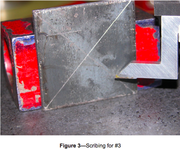
c. For #3, scribe an “X” from corner to corner to find the centre. Then from one corner and its diagonal corner, scribe a line at ½" (Figure 3), then centre-punch the three intersections
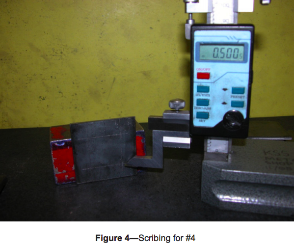
d. For #4, scribe an “X” from corner to corner. From each corner, scribe a line toward the centre at ½" (Figure 4), then centre-punch the four intersections (do not centre-punch the centre of the “X”).
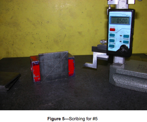
e. For #5, scribe an “X” from corner to corner to find the centre. From each corner, mark a line at ½" (Figure 5), then centre-punch the five intersections.
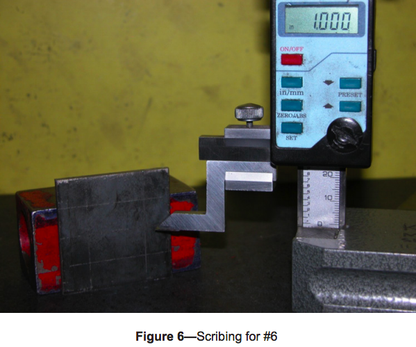
f. For #6, using a hermaphrodite caliper (or other available layout tools) set at ½", scribe parallel lines around all four sides of square. Scribe a line with a hermaphrodite caliper at 1" from one edge (Figure 6), then centre-punch all six intersections.
Part 2: Drilling
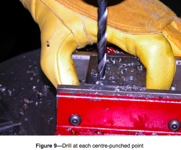
1. Drill through all centre-punch marks on a drill press with a ¼" drill bit. For a variation, drill #6 with a bigger bit and make that side of the die into a pencil holder.
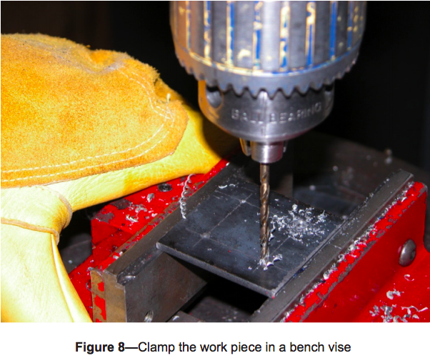
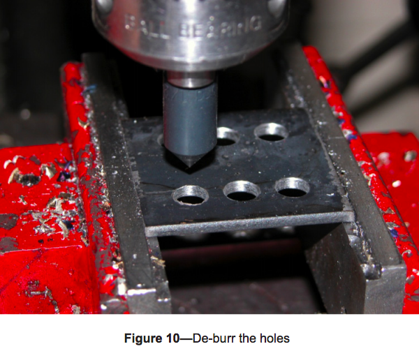
2. De-burr all drill holes on both sides of the stock with a file, sandpaper, de-burring tool, or countersink.
Part 3: Set-up and Welding
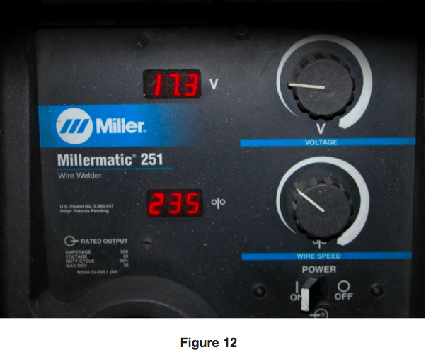
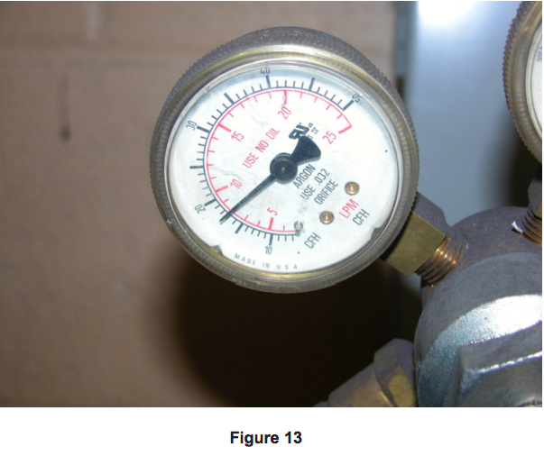
1. Set the welder’s voltage, wire speed, and shielding gas pressure according to the manufacturer’s specifications for ⅛" steel (SEE DEMO with teacher)
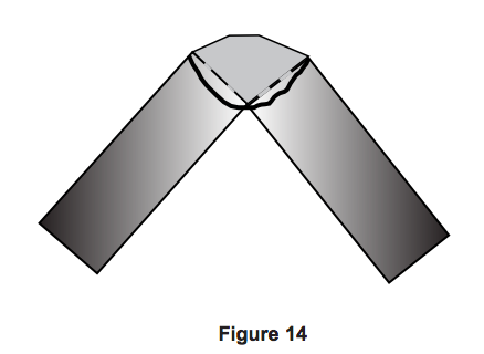
2. Using a 90° welding magnet, set up pieces #4 and #5 in an open corner joint weld position (Figure 14).
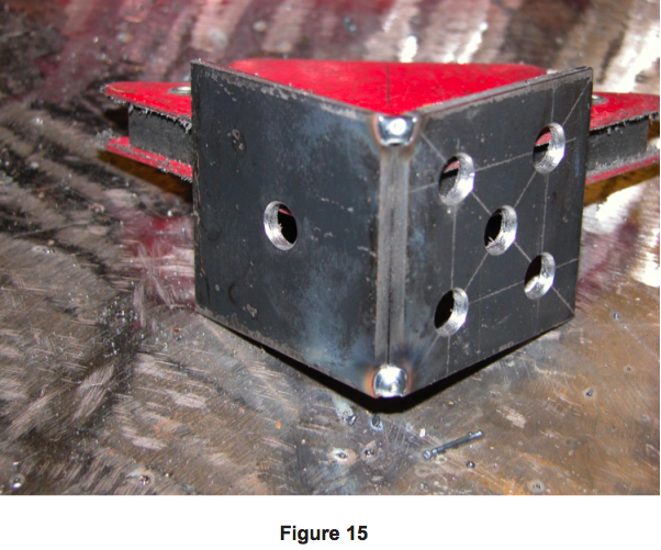
3. Tack pieces #4 and #5 together in an L shape using the MIG welder (Figure 15).
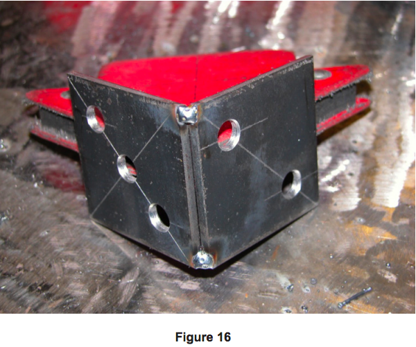
4. Repeat the previous two steps with pieces #2 and #3 (Figure 16).
5. Place the tacked #4 and #5 on their side along with the tacked #2 and #3 on their side. Orient them toward each other to create a box/cube with no top or bottom.
6. Tack the assembly together with an outside corner joint.
7. Place #6 on top of the assembly and tack it into place, leaving four outside corner joints.
6. Tack the assembly together with an outside corner joint.
7. Place #6 on top of the assembly and tack it into place, leaving four outside corner joints.
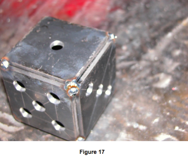
8. Flip the die over and place #1 piece on top. Tack it into place, leaving four outside corner joints (Figure 17).
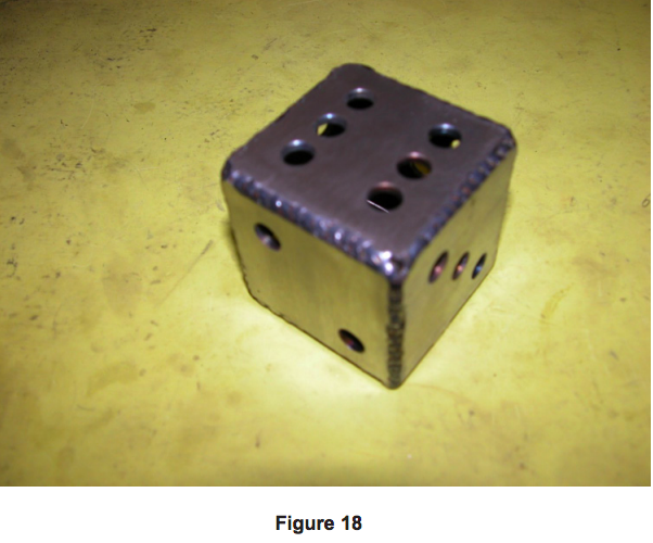
9. Fully weld all 12 outside corner joints (Figure 18).
9. Fully weld all 12 outside corner joints (Figure 18).
Part 4: Finishing
1. Using a bench grinder or belt sander, clean up all welds, leaving gently rounded corners.
2. Re-weld all gaps and porosity discovered after grinding/sanding, then grind/sand the new welds.
3. Using the sander, a file, or sandpaper, smooth out all surfaces to pre-paint quality.
4. Spray paint the die to keep it from rusting.
2. Re-weld all gaps and porosity discovered after grinding/sanding, then grind/sand the new welds.
3. Using the sander, a file, or sandpaper, smooth out all surfaces to pre-paint quality.
4. Spray paint the die to keep it from rusting.
Assessment
• Layout is correct.
• Completed die is welded square.
• Welds have no visible porosity.
•Sanding and grinding lines not seen in paint.
• Safe work habits were displayed.
• Completed die is welded square.
• Welds have no visible porosity.
•Sanding and grinding lines not seen in paint.
• Safe work habits were displayed.
